MOTORBIKE ENGINE SHELL ASSIGNMENT 2

The first step in achieving the outcome of the motorbike engine shell was to use the programs of rhino and grasshopper which would create a mould to work off. These programs proved to be a challenge within our group as no-one had used them before. We played around with the programs for a while and also asked fellow peers to lead us in the right direction, Russell eventually decided to show us how to use the program, grasshopper being used as the equation behind what was shown in rhino.
Once we had the ability to use rhino ourselves we exported the file and imported it into the program 'slicer' which enabled us to dissect the mould into a grid like shape with x and y axes. We made the gaps that the x and y would slot into at 3.8mm and our material of plywood was set at 3mm. This close proximity in sizing made it tricky at times when it eventually came to slotting the pieces into one another, but we managed.

Once we had the file in slicer we imported it into illustrator to get the coloring right for the cut through lines (red 255) and the engraving lines (blue 255). When we had altered all of our panels to enable them to work with the laser cutter we began to cut. We had several pieces of 3mm ply.
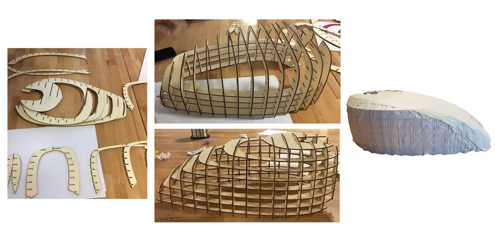
As mentioned above constructing the mould proved to be challenging as the slots for the y axes to fit into the x axes and vice versa were almost the same size as the material it was extremely tight. This resulted in several of the pieces snapping, bending and breaking. We used a hot glue gun and sticky tape to reinforce the structure, which made it sturdy and strong. This was then followed by covering the entire mould in sticky tape to further the solidity of the mould and also give it a flatter surface for us to work on.

MEASURING
Once we had the mould completed we used paper to cover it which would determine how much aluminium we would need. We covered the entirety of the mould and then ruled out lines to determine where the 4 different parts of the engine would be. We then cut the paper to reflect this and drew an outline of the paper onto an aluminium sheet. This was then cut out to replicate the shape of the paper. I placed a 5mm gap around the outer edge of my paper to allow for error room. Once the shape was cut I then went back to the paper to determine the curvature of the mould. I ruled out the curved lines on the paper and then transferred this back to the metal sheet.

SHRINKING/STRETCHING
Once the metal was cut to size I began to shape it. I used the wooden mallet to begin by shrinking the outer edges of the top of the piece as well as around the front section, this instantly started to curve the metal into the shape I was hoping for. I continued to roll the metal out on the english wheel to decrease the intensity of the curvature made by the shrinking. I went back and forth a few times doing this. When i realised the top section of the metal had too much of a surface i decided to shrink it in the shrinking machine. This helped a lot with the entire form and ability of my piece.

FITTING
I referred back to the mould quite regularly until my piece of aluminium could fit to the structure on its own. Once my piece was almost complete in its shaping we began to position the top piece with mine so that we could work out how to fit it as exact as possible.

SANDING
Once my shaping was complete I began to sand my material back. I used 320, 800 and 1500 to do so. At first I didn't use water with these but eventually did so. I also used the file to file back the edges of my material, giving the bottom of my shape a flat edge.

SANDING
I added water and this made the sanding process much easier and efficient. The areas in which I used the shrinking machine on were difficult to hand sand and so I used the file and then the electrical sander, firstly with a harder grit sand paper and gradually back to the 320 sandpaper. This almost completely removed the shrinking marks from my material.

FINAL
This is the final form sitting flush to the moulded motorbike engine.

FINAL
This is the final form meeting with the top piece of the motorbike engine.

FINAL
This is the final form meeting with all other pieces of the motorbike engine. My piece is the piece on the viewed side of both of these images.


Comments
Post a Comment